Hi, for a research project I came across the problem of how to render the edges of triangles as thick lines in the fragment shader.
TL;DR: OpenGL Shader code for thick, shape independent rendering of triangle edges
Existing methods for rendering triangle edges typically use the line rendering mode of OpenGL. This, however, only renders lines that are exactly 1 pixel thick in general. The presented method can draw edges with arbitrary thickness.
The implementation uses Geometry shaders and Fragment shaders. For an introduction, see e.g. http://www.geeks3d.com/20111111/simple-introduction-to-geometry-shaders-glsl-opengl-tutorial-part1/.
Barycentric coordinates
The method that I’m going to use are Barycentric coordinates:
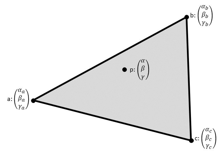
Each vertex \(v\) of the triangle is assigned a 3D vector \((\alpha_v, \beta_v, \gamma_v)^T\). These values are then interpolated by the GPU, leading to the values \((\alpha, \beta, \gamma)^T\) at a point \(p\) inside the triangle.
The naïve way
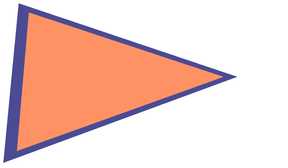
The first idea, most simple idea is to set the barycentric coordinates of the three vertices to the unit vectors, \(a=(1,0,0)^T, b=(0,1,0)^T, c=(0,0,1)^T\). Then draw an edge if any(lessThan(p, threshold)), where any(lessThan(a, b)) returns true if any component of a is less than any component of b, p is the interpolated barycentric coordinate and threshold is a constant value between 0 and 1.
This is the result:
 |
 |
 |
|---|
As one can see, the edges are not independent of the size and shape of the triangle. The more the triangle is stretched, the thinner the edge becomes.
Balance edge lengths
The compensate the dependency on the size, the lengths of the edges have to be included.
Let’s fix the threshold to 1 and modify the values at the vertices. This is exactly the other way round than before.
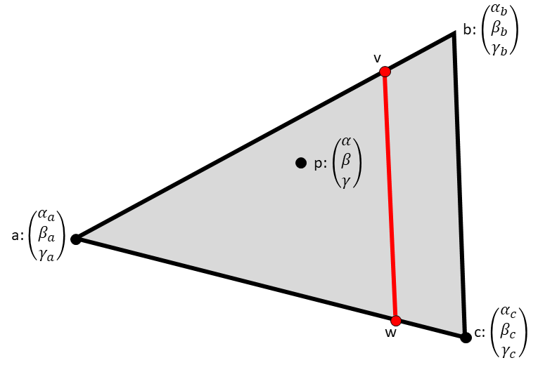
Let \(d\) be the desired thickness of the edge in pixels. Further, set \(\alpha_a\) to zero, so that the position of \(v\) and \(w\), the point where the interpolated first coordinate is exactly 1, is only determined by \(\alpha_b\) and \(\alpha_c\).
By the baricentric interpolation, we have then the following relations:
\(d \stackrel{!}{=} |\overrightarrow{vb}| = |\overrightarrow{ab}| * (1-1/\alpha_b)\)
\(d \stackrel{!}{=} |\overrightarrow{wc}| = |\overrightarrow{ac}| * (1-1/\alpha_c)\)
All length computations are in pixel space.
Solving the above equations for \(\alpha_b\) and \(\alpha_c\) leads to:
\(\alpha_b = \frac{1}{1-\frac{d}{|\overrightarrow{ab}|}}\)
\(\alpha_c = \frac{1}{1-\frac{d}{|\overrightarrow{ac}|}}\)
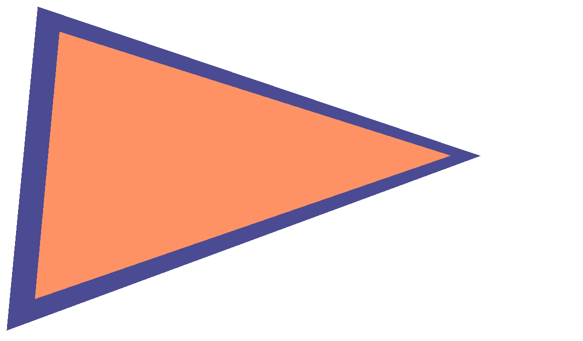
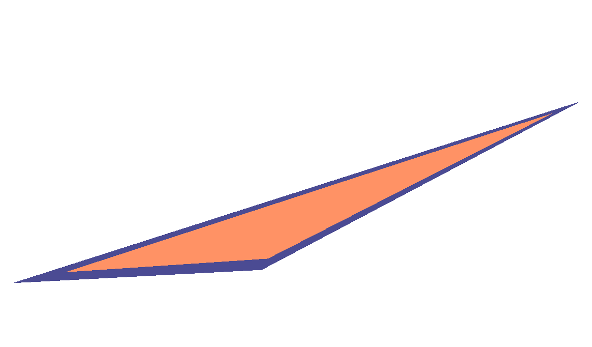
These are the results:
 |
 |
 |
|---|
This is an improvement, the thickness of the edges are constant at the vertices and independent of the length of the edges. But they are still dependent on the shape / amount of shearing.
Balance edge angles
The problem is that the value \(d\) from above is not actually the thickness of the edge. It is instead the distance from the vertex to the inner corner of the edge, indicated with \(d’\) in the picture below:
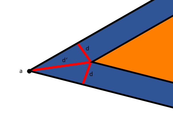
Hence, the missing step is to compute \(d’\) depending on \(d\) and the angle at the vertices:
\(d’ = d / \sin^{-1}(\angle BAC)\)
And repeat that for all three vertices.
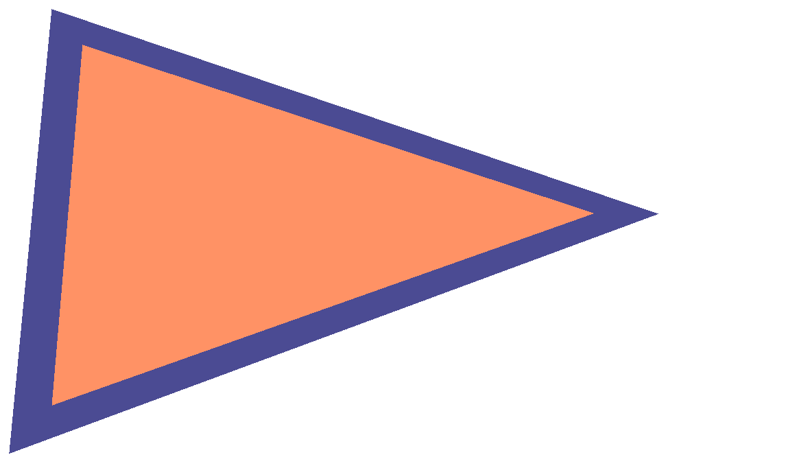
The final results:
 |
 |
 |
|---|
Finally, the thickness of the edges is completely independent of the triangle size and shape.
Depth dependency
So far, all computations were done in 2D screen space. The models, however, are all in 3D space, so we have to think about depth as well. Up to now, the thickness of the edges is independent of the depth or distance from the camera. This might be intended, but sometimes, it is useful to include the depth as well.
The idea is to make the thickness smaller with increasing depth:
\(d” = d’ / |\text{vertexWorldPosition} – \text{cameraPosition}|\)
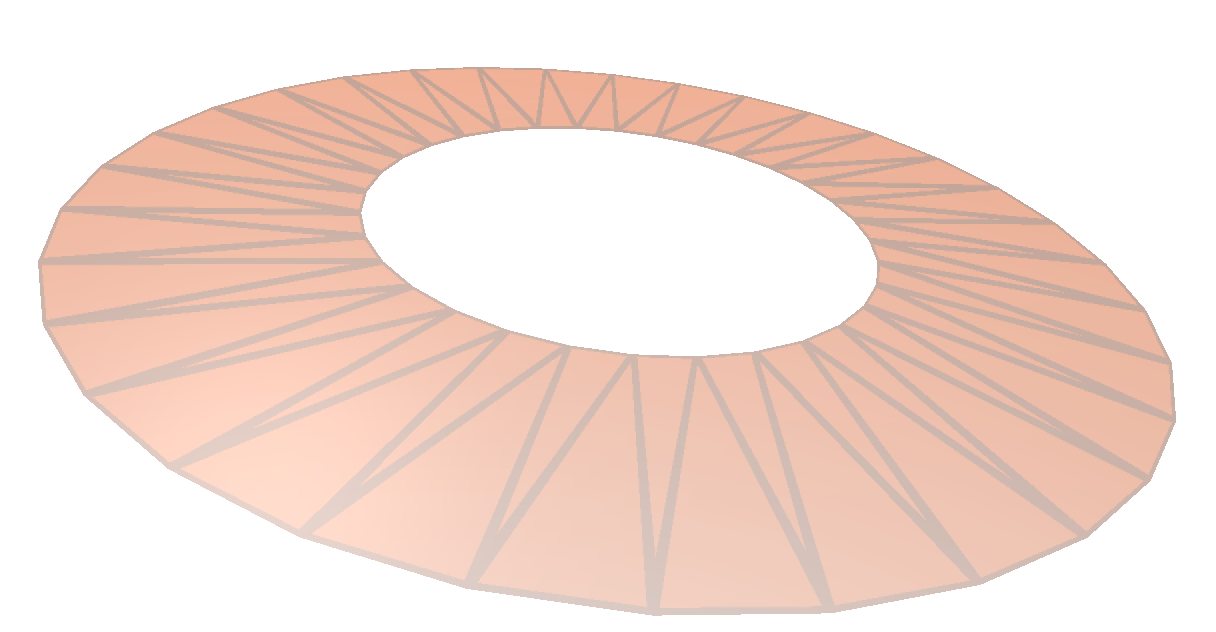
 |
 |
|---|---|
| No depth dependency | With depth dependency |
It’s a bit hard to see, but on the left side, the edge thickness is always constant. On the right side, the edges closer to the camera are thicker, providing a better depth perception.
Final shader code
To wrap this article up, here is the final shader code:
Geometry shader:
uniform ivec2 halfScreenSize;
uniform float edgeWidthGlobal; //the d in the equations above

in vData
{
    vec4 worldPosition;
    vec4 position;
} vertices[];

out fData
{
    vec4 worldPosition;
    vec4 position;
    vec3 edgeCoordinates;
} frag;

void main(void)
{
    //edge coordinates for edge highlighting
    //vertices coordinates in pixel space
    vec2 screenA = halfScreenSize * vertices[0].position.xy / vertices[0].position.w;
    vec2 screenB = halfScreenSize * vertices[1].position.xy / vertices[1].position.w;
    vec2 screenC = halfScreenSize * vertices[2].position.xy / vertices[2].position.w;
    //side lengths in pixel coordinates
    float ab = length(screenB - screenA);
    float ac = length(screenC - screenA);
    float bc = length(screenC - screenB);
    //cosines angles at the vertices
    float angleACos = dot((screenB - screenA) / ab, (screenC - screenA) / ac);
    float angleBCos = dot((screenA - screenB) / ab, (screenC - screenB) / bc);
    float angleCCos = dot((screenA - screenC) / ac, (screenB - screenC) / bc);
    //sines at the vertices
    float angleASin = sqrt(1 - angleACos*angleACos);
    float angleBSin = sqrt(1 - angleBCos*angleBCos);
    float angleCSin = sqrt(1 - angleCCos*angleCCos);

    //desired edge width in pixels
#ifdef DRAW_EDGES_DEPTH_DEPENDENT
    //depth-dependency
    vec3 edgeWidth = vec3(
        edgeWidthGlobal/ length(vertices[0].worldPosition.xyz - camera.position.xyz),
        edgeWidthGlobal/ length(vertices[1].worldPosition.xyz - camera.position.xyz),
        edgeWidthGlobal/ length(vertices[2].worldPosition.xyz - camera.position.xyz)
    );
#else
    vec3 edgeWidth = vec3(edgeWidthGlobal);
#endif
    //compute edge coordinates
    //clamping is necessary to catch the case if the edge thickness is larger than the triangle size
    vec3 edgeCoordinates[3];
    edgeCoordinates[0] = vec3(
        0,
        1 / (1 - min(0.99999, edgeWidth.x / (ab * angleASin))),
        1 / (1 - min(0.99999, edgeWidth.x / (ac * angleASin)))
    );
    edgeCoordinates[1] = vec3(
        1 / (1 - min(0.99999, edgeWidth.y / (ab * angleBSin))),
        0,
        1 / (1 - min(0.99999, edgeWidth.y / (bc * angleBSin)))
    );
    edgeCoordinates[2] = vec3(
        1 / (1 - min(0.99999, edgeWidth.z / (ac * angleCSin))),
        1 / (1 - min(0.99999, edgeWidth.z / (bc * angleCSin))),
        0
    );

    //pass-through other parameters
    for (int i=0; i<3; ++i)
    {
        frag.worldPosition = vertices[i].worldPosition;
        frag.position = vertices[i].position;
        frag.edgeCoordinates = edgeCoordinates[i];
        gl_Position = vertices[i].position;
        EmitVertex();
    }
    EndPrimitive();
}
Fragment shader:
uniform vec4 faceColor;
uniform vec4 edgeColor;
in fData
{
    vec4 worldPosition;
    vec4 position;
    vec3 edgeCoordinates;
} frag;

void main() {
    vec4 color;
    if (any(greaterThan(frag.edgeCoordinates,vec3(1)))) {
        color = edgeColor;
    } else {
        color = faceColor;
    }
    gl_FragColor = color;
}
That’s it.
Thank you to all readers who made it so far 😉